Trunnion Mounted <a href='/tag/ball-valve' target='_blank' class='key-tag'><font><strong>ball valve</strong></font></a> Working Principle, Design, Advantages and Specifications
Trunnion Mounted Ball Valve Working Principle: Complete Technical Guide
Trunnion mounted ball valves are critical components in modern pipeline and process systems, especially in oil and gas, petrochemical, power generation, and transmission pipelines. This guide explains the working principle of trunnion mounted ball valves, their design features, advantages, common configurations, and typical specifications in a structured and SEO-friendly format.
A trunnion mounted ball valve is a quarter-turn shut-off valve where the ball is supported by trunnions (upper and lower shafts or journals) that hold the ball firmly in position. Unlike a Floating ball valve, the ball in a trunnion mounted design does not move downstream under pressure. Instead, the seats are spring-loaded or pressure-energized to provide tight sealing against the fixed ball.
In high-pressure and large-size pipelines, trunnion mounted ball valves are preferred because they reduce operating torque, minimize seat wear, and offer reliable bi-directional sealing. These valves are widely used in transmission pipelines, block valves, terminal stations, compressor stations, and process plants.
Key characteristics of trunnion mounted ball valves include:
Option for Double Block and Bleed (DBB) and Double Isolation and Bleed (DIB)
Available in soft-seated and metal-seated designs
2. Key Components of a Trunnion Mounted Ball Valve
Understanding the main components helps explain the working principle of a trunnion mounted ball valve.
Component
Description
Function in Trunnion Ball Valve
Body
Main pressure-containing shell, can be two-piece or three-piece forged or cast construction.
Houses ball, seats, and trunnion; provides pressure boundary.
Ball
Drilled sphere with a through-bore matching or reduced from the pipe diameter.
Controls flow by aligning or blocking the bore with the line.
Trunnion (Top and Bottom)
Mechanical supports that hold the ball at the top and bottom, integral or separate pieces.
Provide pivot points, reduce ball movement, and absorb line pressure loads.
Seats
Replaceable sealing elements, either soft or metal, spring-loaded or pressure-energized.
Seal against the ball to ensure zero or low leakage shut-off.
Seat Springs
Helical springs or spring packs behind seats.
Push seats toward the ball to maintain contact at low pressure or in the absence of differential pressure.
Stem
Connection between the actuator or handle and the ball.
Transmits torque to rotate the ball 90°.
Stem Seals & Packing
O-rings, packing rings, and gland components.
Prevent leakage along the stem to atmosphere.
Body Seals
O-rings, gaskets between body pieces and closures.
Provide sealing at body joints in split-body or top-entry designs.
Anti-blowout Stem Design
Mechanical retention feature that prevents the stem from being ejected.
Improves safety according to recognized standards.
Drain and Vent Connections
Valved ports on body cavity, often for DBB and DIB configurations.
Allow draining, venting, or bleeding of the body cavity for testing and maintenance.
Actuation Interface
ISO top flange or custom mounting pad.
Allows mounting of gearboxes, pneumatic, hydraulic, or electric actuators.
3. Working Principle of Trunnion Mounted Ball Valve
The working principle of a trunnion mounted ball valve is based on a fixed, supported ball and movable seats that create a tight seal under pressure. The core mechanism involves quarter-turn rotation and pressure-assisted seat sealing.
3.1 Flow Control by Quarter-Turn Rotation
Trunnion mounted ball valves use a 90-degree rotation of the ball to switch between open and closed positions:
Open Position (0° or 90°, depending on design): The bore of the ball is aligned with the pipeline axis. Fluid flows through the full or reduced bore with minimal pressure drop.
Closed Position (90° or 0°): The solid part of the ball blocks the flow path. The seats seal against the ball, preventing flow in one or both directions.
3.2 Role of Trunnions in the Working Principle
In a trunnion mounted ball valve, the ball is supported at two points:
The upper trunnion connects to the stem or is integral with it.
The lower trunnion supports the bottom of the ball.
This support arrangement ensures that:
The ball does not move downstream under high differential pressure.
The operating torque is reduced because the line pressure load is taken by the trunnions, not by the seats.
The contact pressure between seat and ball can be controlled more effectively.
3.3 Seat Movement and Pressure-Energized Sealing
Unlike floating ball valves where the ball moves toward the downstream seat, in trunnion ball valves the seats move toward the ball. This movement occurs through spring force and differential pressure.
The sealing mechanism operates in two phases:
Low-Pressure Sealing: At low differential pressures, metallic or elastomeric springs behind the seats push them into contact with the ball, ensuring initial sealing.
High-Pressure Sealing: As line pressure increases, pressure acts on the back side of the upstream seat, forcing it more tightly against the ball. This pressure-energized effect enhances the seal.
3.4 Flow Direction and Bi-Directional Sealing
Trunnion mounted ball valves can be designed for:
Uni-directional sealing: Effective sealing mainly in one flow direction.
Bi-directional sealing: Effective sealing in both directions, often required in pipeline block valves.
Many modern trunnion ball valves are bi-directional, meaning they can provide tight shut-off whether flow comes from upstream or downstream side. Depending on design, they can be classified as DBB or DIB valves (discussed in a later section).
3.5 Cavity Relief and Body Cavity Pressure
The cavity between the seats and around the ball (body cavity) may become pressurized due to thermal expansion or trapped media. To prevent overpressure, trunnion mounted ball valves are often designed with:
Self-relieving seats: The seat will unseal slightly at a defined pressure differential, allowing cavity fluid to relieve to the downstream side.
External relief connections: Optional relief valves or bleed lines connected to the body cavity.
This cavity relief remains part of the working principle because it influences seat design and sealing direction.
4. Floating Ball Valve vs Trunnion Mounted Ball Valve
Understanding the difference between floating and trunnion mounted ball valves is crucial for proper valve selection. Both are ball valves, but they employ different working principles for sealing and load distribution.
Feature
Floating Ball Valve
Trunnion Mounted Ball Valve
Ball Support
Ball is held only by the seats and stem; it can move slightly downstream.
Ball is supported by upper and lower trunnions and does not move downstream.
Sealing Principle
Line pressure pushes the ball against the downstream seat to form a seal.
Seats move toward the fixed ball; pressure and springs energize the seats.
Typical Size Range
Small to medium sizes (typically up to DN 200 / 8″).
Medium to very large sizes (DN 50–DN 1400 and above).
Pressure Range
Low to medium pressures.
Medium to very high pressures, including high-pressure pipeline classes.
Operating Torque
Higher torque at high pressures because seats carry the pressure load.
Higher seat wear and deformation risk at high differential pressure.
Reduced seat wear thanks to stable ball position and optimized contact pressure.
Applications
General utility, low-pressure industrial services.
Pipeline isolation, critical process services, high-pressure systems.
Cost
Lower cost for small sizes.
Higher initial cost but more economical for large sizes and high pressures.
5. Sealing Mechanism and Seat Design
The sealing mechanism of a trunnion mounted ball valve depends greatly on the seat and ball interface. Two main categories are soft-seated and metal-seated designs.
5.1 Soft-Seated Trunnion Ball Valves
Soft-seated trunnion ball valves use polymeric or elastomeric materials such as PTFE, reinforced PTFE, PEEK, or other plastics and rubbers as the primary sealing element. Typical features include:
Very low leakage: Capable of achieving tight shut-off (often leakage rate A or ISO 5208 Rate A).
Lower operating torque: Due to softer seat materials and smooth contact with the ball.
Temperature limitations: Generally limited by the soft material’s thermal stability.
Chemical compatibility: Seat composition chosen according to media (e.g., hydrocarbons, corrosive fluids).
5.2 Metal-Seated Trunnion Ball Valves
Metal-seated trunnion mounted ball valves use metallic seat rings and often coated balls (e.g., hardfacing, tungsten carbide). They are selected when:
Operating temperatures exceed the limit of soft seats.
Media are abrasive, erosive, or contain solids.
Fire-safe performance is critical.
Characteristics include:
Higher allowable temperature range.
Increased wear resistance in harsh conditions.
Slightly higher leakage rates compared to soft-seated designs, depending on class.
5.3 Single Piston Effect (SPE) and Double Piston Effect (DPE) Seats
Trunnion mounted ball valves often apply specific seat geometries known as Single Piston Effect (SPE) and Double Piston Effect (DPE) to manage sealing and cavity relief.
Seat Type
Sealing Principle
Effect on Cavity Relief
Typical Use
Single Piston Effect (SPE)
Pressure on one side of the seat creates a force that both seals and allows the seat to move away at higher cavity pressure.
Automatic body cavity pressure relief to the line when cavity pressure exceeds line pressure.
Common in DBB Valves and where self-relieving seats are required.
Double Piston Effect (DPE)
Pressure from either side of the seat pushes it toward the ball, enhancing sealing in both directions.
Cavity pressure is not self-relieving; separate relief device needed.
Used where high integrity double isolation is required (DIB functionality).
5.4 Fire-Safe Sealing Concept
Fire-safe trunnion mounted ball valves are designed such that if soft seals are destroyed by fire, secondary metal-to-metal seals maintain a certain level of tightness to prevent extensive leakage. Fire-safe certification typically follows internationally recognized standards.
6. Main Design Features of Trunnion Ball Valves
Modern trunnion mounted ball valves incorporate multiple design features to meet industrial requirements for safety, performance, and maintainability.
6.1 Body Construction Types
Two-Piece Split Body: Body is split along a vertical or horizontal plane, with bolted joint. Common in medium and large sizes.
Three-Piece Body: Central body section containing ball and seats with two end closures. Facilitates maintenance and seat replacement.
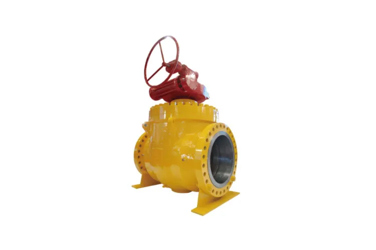
Top Entry: Bonnet or cover on top enables access to internals without removing the valve from the line, suitable for welded-in Pipeline Valves.
Fully Welded Body: No external body bolts; body joints are welded. Recommended for buried or subsea pipelines where leakage from body joints must be minimized.
6.2 Bore Types
Full Bore (Full Port): The ball bore matches the nominal pipe diameter. Minimizes pressure drop and allows pigging in pipelines.
Reduced Bore (Reduced Port): Ball bore is smaller than pipe ID. Reduces weight and cost; suitable when pressure drop is acceptable.
6.3 Stem Design
Anti-Blowout Stem: Stem is inserted from inside the body and retained so it cannot be expelled under pressure.
ISO Mounting Pad: Standard interface for actuators according to ISO 5211 or similar patterns.
Low Emission Packing: Use of advanced packing systems to meet fugitive emission requirements.
6.4 Sealant Injection and Emergency Sealing
Many trunnion mounted ball valves in critical services provide:
Stem sealant injection fittings: Allow temporary sealing enhancement if packing is damaged.
Seat sealant injection: Provides emergency secondary sealing between seat and ball in case of primary seal damage.
6.5 Anti-Static and Grounding Devices
To prevent static buildup due to fluid flow and friction between ball and seats, anti-static devices are added between:
Stem and body.
Ball and stem.
This ensures electrical continuity and reduces risk of sparks in flammable environments.
7. Relevant Standards and Design Codes
Trunnion mounted ball valves are engineered and tested in accordance with internationally recognized standards. Common standards include:
API 6D: Specification for pipeline and piping valves; widely referenced for trunnion ball valves.
API 608: Metal ball valves for general refinery and chemical service.
The pressure–temperature rating of a trunnion mounted ball valve depends on material, design standard, and end connection. The following table provides generic examples based on common carbon steel materials:
Pressure Class (ASME)
Approx. Max Pressure at 38°C (Carbon Steel)
Typical Application Range
Class 150
~19.6 bar (285 psi)
Low to medium pressure pipeline and process systems.
Class 300
~51.0 bar (740 psi)
Medium pressure oil and gas, chemical plants.
Class 600
~102.0 bar (1480 psi)
High pressure transmission lines and process units.
Class 900
~153.0 bar (2220 psi)
High pressure critical applications.
Class 1500
~255.0 bar (3705 psi)
Very high pressure upstream and subsea environments.
Class 2500
~425.0 bar (6170 psi)
Extreme pressure critical service.
Actual ratings must always be confirmed from the applicable design standard and material-specific charts. Soft seat materials may further limit maximum temperature.
9. Common Materials of Construction
Trunnion mounted ball valves are manufactured in a wide range of materials to handle different fluids, pressures, and temperatures.
Component
Typical Materials
Selection Considerations
Body & Closure
Carbon steel (A105, A216 WCB), low-temperature carbon steel (LCC), stainless steel (CF8M, F316), duplex and super duplex, alloy steels.
Chosen for pressure rating, temperature, corrosion resistance, sour service compliance.
Ball & Trunnion
Stainless steel, high-strength alloy steel, corrosion-resistant overlay or coatings.
Hardness, wear resistance, corrosion protection to match medium and service severity.
Compatibility with media, temperature rating, fire-safe design.
10. End Connections and Face-to-Face Dimensions
Trunnion mounted ball valves can be supplied with various end connections to suit pipeline requirements.
10.1 Common End Connections
Flanged Ends: Conform to ASME B16.5 or ISO standards; easy installation and removal.
Butt Weld Ends: Conform to ASME B16.25; preferred in high-pressure pipelines and buried service.
Hub or Clamp Connections: Used in offshore and specialized systems.
10.2 Face-to-Face and End-to-End Dimensions
Face-to-face and end-to-end dimensions for flanged and butt weld trunnion ball valves often follow:
API 6D
ASME B16.10
ISO 5752
Standardized dimensions simplify replacement and interchangeability in pipeline systems.
11. Operation: Manual, Gear, and Actuated Trunnion Ball Valves
Because trunnion mounted ball valves often handle high pressure and large diameters, their operating torques can be substantial. Different operation methods are implemented:
11.1 Manual Lever Operation
Small-size trunnion ball valves at lower pressure ratings can be operated with a simple lever handle, allowing quick quarter-turn operation.
11.2 Gearbox Operation
For larger sizes or higher pressures, a manual gearbox is used:
Reduces required hand force by providing mechanical advantage.
Enables controlled, slow operation to prevent water hammer.
11.3 Actuated Operation
Automated trunnion mounted ball valves are common in modern process control and pipeline systems. Common actuators include:
Pneumatic actuators: Suitable for fast operation and remote control.
Hydraulic actuators: Used for high-torque, high-pressure applications, including subsea and Emergency Shutdown Valves.
Electric actuators: Ideal where pneumatic or hydraulic supplies are limited and precise control is required.
Actuated trunnion ball valves may be configured as on/off, fail-safe (fail-open or fail-close), or modulating control valves when combined with positioners.
12. Typical Applications of Trunnion Mounted Ball Valves
Trunnion mounted ball valves are used in a wide range of industrial sectors due to their robust design and reliable sealing performance.
Oil and Gas Transmission Pipelines: Mainline block valves, station isolation, scraper traps.
Refineries and Petrochemical Plants: Process unit isolation, tank farm manifolds.
Offshore Platforms: Wellhead manifolds, riser systems, topside and subsea isolation.
Power Generation: Fuel gas lines, cooling water systems, auxiliary services.
Chemical and Fertilizer Plants: Corrosive and toxic service isolation requiring reliable shut-off.
Liquefied Natural Gas (LNG) and Cryogenic Service: Special cryogenic trunnion ball valves with extended bonnets.
13. Advantages of Trunnion Mounted Ball Valves
Using trunnion mounted ball valves in demanding applications offers multiple technical and economic benefits.
Advantage
Description
Impact on System Performance
Low Operating Torque
Trunnions absorb pressure-induced loads, reducing friction between ball and seats.
Easier manual operation and smaller, more economical actuators.
Reliable Sealing at High Pressure
Pressure-energized seats maintain tight seal across a wide pressure range.
Reduced leakage risk, improved safety in critical services.
Suitable for Large Diameter Pipelines
Mechanical support prevents ball deformation and seat overload.
Economical and safe solution for large pipe sizes.
DBB and DIB Capability
Design can provide double block and bleed or double isolation and bleed functionality.
Enhanced isolation for maintenance, testing, and safety-critical operations.
Long Service Life
Reduced seat wear due to controlled contact pressures.
Lower total cost of ownership and fewer shutdowns for maintenance.
Fire-Safe and Emission Control
Compliance with fire-test and fugitive emission standards where required.
Improved environmental performance and regulatory compliance.
14. Selection Considerations
Selecting the correct trunnion mounted ball valve for a given service requires evaluation of several factors.
14.1 Process Conditions
Fluid type (liquid, gas, multiphase, corrosive, dirty service).
Operating pressure and temperature range.
Presence of solids, sand, or particulates.
Required shut-off class and leakage requirements.
14.2 Design Requirements
Needed bore type (full or reduced bore) and piggability.
Pressure class and connection type (flanged, welded, hub).
Compliance with specific standards (API 6D, ISO, regional regulations).
Need for DBB or DIB functionality and cavity relief method.
14.3 Operation and Control
Manual versus automatic operation.
Available utilities (air, hydraulic fluid, electricity).
Fail-safe requirements and emergency shutdown logic.
14.4 Environmental and Safety Considerations
Fire-safe and fugitive emission requirements.
Hazardous area classification for actuators and accessories.
Sour service compliance (e.g., sour gas with H2S).
15. Maintenance, Inspection, and Safety Considerations
Proper maintenance ensures long-term reliability of trunnion mounted ball valves.
15.1 Routine Inspection
Check for external leakage at body joints, stem packing, and end connections.
Verify actuation performance and stroke time.
Inspect for corrosion, coating damage, and mechanical damage.
15.2 Seat and Seal Maintenance
Regularly exercise the valve to prevent sticking.
Use sealant injection systems only as a temporary emergency measure, not as a permanent solution.
In top-entry or three-piece designs, seats and seals can often be replaced without removing the valve from the line.
15.3 Safety During Operation
Ensure system is depressurized before maintenance or disassembly.
Confirm correct valve position before performing any pipeline work.
Follow lockout-tagout procedures in automated systems.
16. Example Specification Tables for Trunnion Mounted Ball Valves
The following example tables illustrate typical specification data that engineers may reference when selecting or comparing trunnion mounted ball valves. Values are indicative and should not be used as design data.
16.1 Example Dimensional and Operational Data
Nominal Size (DN / NPS)
Bore Type
Pressure Class
End Connection
Approx. Face-to-Face (mm)
Typical Operating Torque (Nm)
DN 50 / 2″
Full Bore
Class 300
Flanged
250–300
60–100
DN 150 / 6″
Full Bore
Class 600
Flanged
500–600
400–700
DN 300 / 12″
Full Bore
Class 600
Butt Weld
800–900
1500–2500
DN 600 / 24″
Full Bore
Class 300
Butt Weld
1300–1500
4000–7000
16.2 Example Material and Design Summary
Item
Description
Typical Option 1
Typical Option 2
Body Material
Main valve body and closures
ASTM A105 (carbon steel)
ASTM A182 F316 (stainless steel)
Seat Type
Primary sealing element
Soft seat (RTFE)
Metal seat (hardfaced)
Sealing Effect
Seat geometry
SPE (Single Piston Effect)
DPE (Double Piston Effect)
Fire-Safe Design
Compliance with fire test
According to API 607
According to ISO 10497
Operation
Actuation method
Manual gearbox
Pneumatic actuator
17. Frequently Asked Questions About Trunnion Mounted Ball Valve Working Principle
17.1 Why choose a trunnion mounted ball valve instead of a floating ball valve?
Trunnion mounted ball valves are preferred for high-pressure and large-diameter applications because they offer lower operating torque, reduced seat wear, and more reliable sealing. The fixed ball supported by trunnions ensures that pressure loads are transmitted to the valve body rather than to the seats, improving durability and safety.
17.2 How does the working principle affect leakage performance?
The working principle relies on spring-loaded and pressure-energized seats that move toward the stationary ball. This ensures a consistent sealing force across a wide pressure range. As a result, trunnion mounted ball valves can achieve very low leakage rates, making them suitable for critical isolation duties.
17.3 Can trunnion mounted ball valves be used for throttling?
Although a trunnion mounted ball valve can momentarily control flow, it is primarily designed as an on/off isolation valve. Prolonged operation in partially open positions may cause uneven seat wear, erosion, or cavitation damage. Where precise flow control is required, dedicated control valves are recommended.
17.4 What is Double Block and Bleed (DBB) in trunnion ball valves?
Double Block and Bleed refers to the ability of a single valve to provide two seating barriers (upstream and downstream) and an intermediate bleed connection to the body cavity. When the valve is closed, both seats isolate the cavity, and the bleed can be used to verify tight shut-off or to depressurize the cavity for maintenance.
17.5 What is Double Isolation and Bleed (DIB)?
Double Isolation and Bleed typically implies that both seats provide tight sealing against pressure from either side, often achieved with Double Piston Effect seats. In a DIB design, the body cavity is not self-relieving, and a separate relief system is used to protect against overpressure.
17.6 Are trunnion mounted ball valves piggable?
Full bore trunnion mounted ball valves are often designed to be piggable, meaning pipeline cleaning and inspection pigs can pass through without obstruction. This is particularly important in oil and gas pipelines where pigging is routine.
Trunnion mounted ball valves play a crucial role in high-pressure and large-diameter pipeline and process systems. Their working principle, based on a fixed, trunnion-supported ball and pressure-energized seats, offers low operating torque, reliable bi-directional sealing, and long service life. Understanding the trunnion mounted ball valve working principle, design features, and selection criteria helps engineers and system designers choose the right valve for safe, efficient, and economical operation in demanding industrial environments.






 Phone